How to read a datasheet
September 27, 2026 · Updated September 30, 2026
Two tables decide whether a part fits your circuit, and they are different tables. Absolute maximum ratings tell you what destroys the part. Recommended operating conditions tell you where it behaves the way the rest of the document claims.
The two tables, and the gap between them
A chip rated for an absolute maximum supply of 6 V and a recommended operating range of 2.7 to 5.5 V is telling you two separate things.
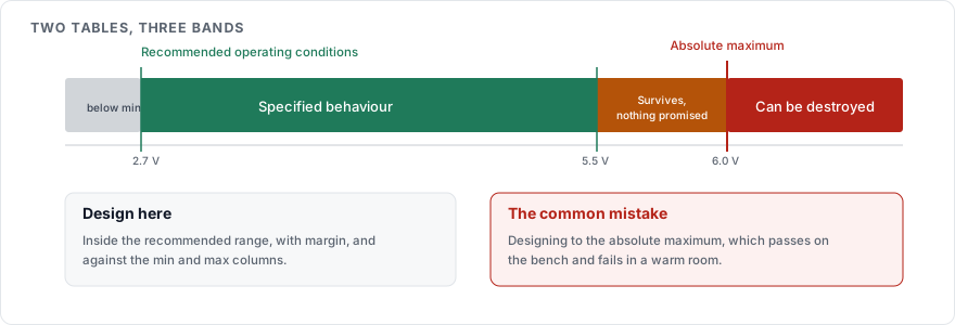
Below 5.5 V it works as specified. Between 5.5 and 6 V it survives, with no promise about accuracy or timing. Above 6 V it is out of warranty and possibly out of existence.
Designing at the absolute maximum is a common mistake, and it produces a circuit that passes on the bench and fails in a warm room. The maximum is a survival limit measured under stated conditions, and it is not a place to operate.
| Table | What it means | How to use it |
|---|---|---|
| Absolute maximum ratings | Exceeding any one of these can destroy the part | Design so the worst case never reaches it |
| Recommended operating conditions | The envelope where the specifications hold | Design inside it, with margin |
| Electrical characteristics | The measured behaviour, with min, typ and max columns | Design against min and max |
Typical is not a specification
The typ column is what one sample measured on one day, and manufacturers state clearly that it is not guaranteed. The min and max columns are the numbers the manufacturer will stand behind.
A circuit that works with the typical value and fails at the maximum will work on most parts from the reel and fail on some, which is the hardest kind of fault to find later. Where a parameter has no min or max at all, the manufacturer is declining to guarantee it. Your design then has to tolerate any value.
Every number has conditions attached
Each line in the electrical characteristics carries test conditions, usually in a column that is easy to skip.
A quiescent current of 2 µA measured at 25 C and 3.3 V tells you nothing about the same part at 85 C, where leakage can be an order of magnitude higher. A propagation delay measured with a 15 pF load says nothing about your board with 80 pF of trace and input capacitance hanging off the pin.
Read the conditions before the value. Where your conditions differ from the test conditions, the number on the page is a starting estimate, and the graphs further into the document are where the manufacturer plots behaviour against temperature and load. Read those at your own conditions.
The first page is a sales pitch
The features list on page one is written to get the part onto a shortlist. Single-digit microamp sleep currents, high accuracy and wide ranges all appear there without the conditions that qualify them.
Treat page one as a table of contents, and the tables in the middle as the contract.
Thermal numbers depend on your board
A package thermal resistance quoted as 45 C/W is measured on a standard test board defined by the JEDEC JESD51 series, usually a four layer board with specified copper areas.
Your two layer board with a small copper pour will run hotter than that figure predicts, sometimes by a wide margin. The number is comparable between parts measured the same way, and it is not a prediction about your layout.
What to check before you commit
The revision date and the errata. A part with a published erratum sheet has known bugs, and those are rarely mentioned in the datasheet body.
The package drawing, against your footprint. Pin 1 orientation and pitch have ended more prototype runs than any electrical parameter.
Whether the lifecycle status says active. A part marked end of life does not belong in a product you plan to ship.
Whether the part number on the page includes your exact suffix. Temperature grade, package and tape reel all live in suffixes, and specifications differ between grades.
Reading order that saves time
Absolute maximum ratings, to see whether your rails and signals are survivable.
Recommended operating conditions, to see whether your design sits inside the envelope.
The two or three electrical parameters your circuit depends on, read at min and max with their conditions.
The graphs for those parameters, at your temperature.
The package drawing and the pinout.
The application circuits near the end, which show what the manufacturer's own engineers did.
Sources
JEDEC JESD51, the standard test environment behind published thermal resistance figures
The manufacturer's errata or product change notices for your exact part number, which the datasheet itself rarely references
How to choose a decoupling capacitor, for the datasheet section most often ignored