How to choose a resistor for an LED
September 27, 2026 · Updated September 30, 2026
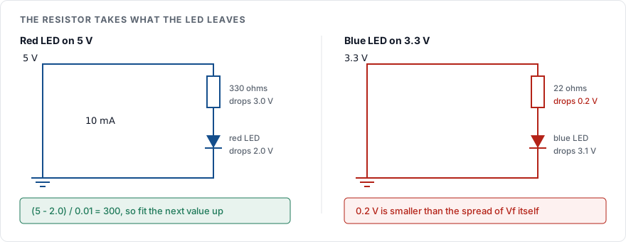
The resistor sets the current. Divide the voltage left over after the LED by the current you want: a red LED on a 5 V rail leaves about 3 V across the resistor, and 3 / 0.01 = 300 ohms for 10 mA, so you fit 330.
Where each number comes from
R = (Vsupply - Vf) / If
Vsupply is the voltage the rail delivers under load. A USB rail marked 5 V sits anywhere from 4.75 to 5.25 V, and a battery falls as it drains.
Vf, the forward voltage, comes from the LED's datasheet, read at the current you intend to use. It varies with the chemistry that makes the colour: red and yellow parts sit near 2 V, while green, blue and white sit near 3 V. It also varies between two parts from the same reel, which is why the datasheet prints a range.
If is your choice, bounded by the datasheet's maximum. Indicator LEDs are visible at 2 mA and bright at 10. Running at the 20 mA maximum buys less brightness than it costs in heat, because the light output per milliamp falls as the current rises.
Round up, never down
The answer is rarely a value you can buy. Resistors come in the E-series of preferred values defined by IEC 60063, and E12 is the series in most parts drawers:
10 12 15 18 22 27 33 39 47 56 68 82
and the same figures scaled by ten, a hundred, a thousand. Round up to the next one. A larger resistor passes less current, which costs you a little brightness. A smaller one passes more, which costs you the LED.
| Supply | Red LED, Vf 2.0 V | Blue or white LED, Vf 3.1 V |
|---|---|---|
| 3.3 V | 130 ohms, fit 150 | 20 ohms, and see below |
| 5 V | 300 ohms, fit 330 | 190 ohms, fit 220 |
| 12 V | 1000 ohms, fit 1k | 890 ohms, fit 1k |
All at 10 mA.
The awkward cell is a blue LED on 3.3 V. The resistor drops 0.2 V, which is less than the part-to-part spread of Vf itself, so the current follows manufacturing tolerance instead of your resistor. One part draws 5 mA and the next draws 40. At that little headroom, use a constant current driver or a higher rail.
Check the power rating
P = If squared, times R
At 5 V and 10 mA through 330 ohms that is 0.0001 x 330 = 33 mW, and any ordinary part is happy.
At 12 V and 20 mA the resistor drops 10 V and carries 20 mA, so 0.0004 x 500 = 200 mW. A 0.25 W part is then running at 80 percent of its rating, where it will be too hot to touch and will drift. Fit a 0.5 W part, or reconsider why a 12 V rail is driving an indicator.
The proportion worth remembering: the higher the supply sits above the LED, the more of your power the resistor turns into heat. A 12 V rail lighting a 2 V LED wastes five sixths of it.
Why the resistor is there at all
An LED is a diode, so its current climbs very steeply with voltage past the knee. Tenths of a volt separate dim from dead. Nothing inside the LED limits its own current, and as it warms its forward voltage falls, which draws more current, which warms it further.
The resistor breaks that loop. Once it is dropping a volt or two, a small change in Vf changes the current by a small fraction of itself, which is the same reason the 0.2 V case above fails.
Two LEDs, two resistors
Putting two LEDs in parallel behind one resistor looks economical and does not work. Their forward voltages will differ, so the one with the lower Vf takes more of the current, runs hotter, and drops further still. One LED is bright and the other is dim, and the bright one fails first.
Give each parallel LED its own resistor. LEDs in series are a different matter and carry the same current by definition: add their forward voltages, keep a volt or two of headroom, and size one resistor for the string. Three white LEDs at 3.1 V need 9.3 V before the resistor does anything, so they belong on 12 V and not on 5.
Sources
IEC 60063, the preferred number series that defines E12, E24 and the rest
The forward voltage and maximum current for your exact part, from its manufacturer's datasheet, which is the only place those numbers are right
How to read a resistor colour code, for identifying the part once it is out of the bag